5. BDC Modeling Tools
After defining the entity
and service, the BDC model can be created. The BDC model defines how to
connect to the data source and how it can be queried. It also defines
the type of information it returns. The BDC Explorer and the BDC
Designer are used to define the BDC model. Both of these new VS 2010
components are described ahead.
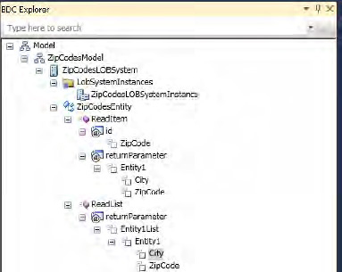
5.1. BDC Explorer
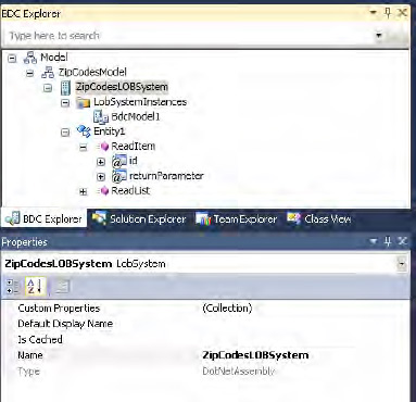
VS 2010 extends the windows list with the BDC Explorer, shown in Figure 4. This window is used to create or edit the BDC model.
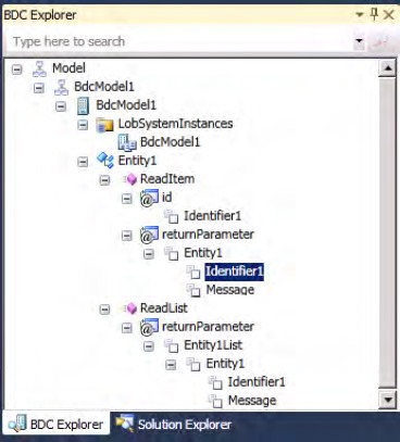
Just like with Solution
Explorer and class view windows, the BDC Explorer is linked to the
Properties window. It shows the relevant properties allowing the
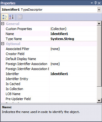
developer to view and edit the BDC model. Figure 5
demonstrates this. When Identifier 1 is selected in the BDC Explorer,
the corresponding properties are displayed in the Properties window.
.5.2. BDC Designer
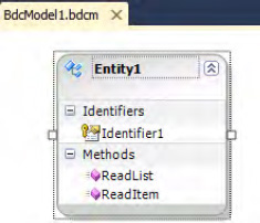
VS 2010 includes the BDC Designer (Figure 6).
This designer window allows the developer to create and edit a BDC
model. The BDC Designer works the same way as the BDC Explorer regarding
the Properties window.
6. Defining the BDC Model
Defining a BDC model is
essentially to define the mapping between your .NET Assembly Connector
and the BDC. In this series of steps, the mappings between the .NET
Assembly Connector and the BDC are defined. To create the mapping,
double-click the BDC Explorer to open the BDCModel1.bdcm
file in Solution Explorer. The BDC Designer will then open and be
visible. From the View menu, select Other Windows. Then click BDC
Explorer to open the window.
6.1. Configuring the BDC Model and LOB System
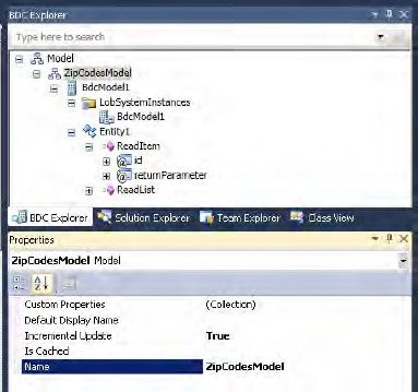
Rename the BDC model to ZipCodesModel, as shown in Figure 7. Right-click the second node from the top, named BdcModel1, and click Properties. Change the Name property to ZipCodesModel in the Properties window.
The third node from the top (the LOB system) should also be renamed. Change the Name property to ZipCodesLOBSystem using the Properties window, as shown in Figure 8.
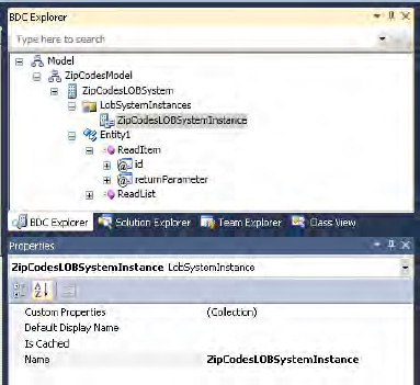
The fifth node from the top
(the LOB system instance) should be renamed to ZipCodesLOBSystemInstance
by using the Properties window to change its Name property, as shown in Figure 9.
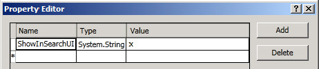
The ShowInSearchUI
property on the ZipCodesLOBSystemInstance must be set to allow the
ZipCodesLOBSystemInstance to be crawled and searched by the SharePoint
search service. If the LOBSystemInstance should not be crawled or
searched, this property does not need to be changed. To set the ShowInSearchUI property on the ZipCodesLOBSystemInstance, click the ZipCodesLOBSystemInstance
node in the BDC Explorer. Then click the button in the Custom
Properties row in the Properties window. Use the Properties Editor to
set the ShowInSearchUI property. Give it the data type System.String and set the value to x, as shown in Figure 10. Click OK.
6.2. Configuring the Entity and Entity Methods
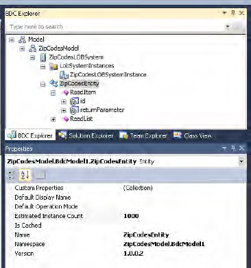
The BDC model entity should
be renamed to match the entity defined in the .NET Assembly Connector.
This is done by selecting Entity1 from the BDC Explorer. Then change the
Name property to ZipCodesEntity in the Properties window, as shown in Figure 11.
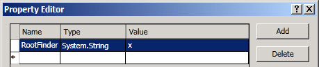
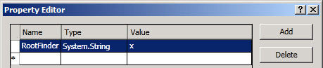
The RootFinder
property on the Finder method must be set to specify the Finder method
used to enumerate the items to crawl. If the Finder method shouldn't be
used for crawling, this property can be ignored and left unset. The RootFinder property on the Finder method is set in the BDC Explorer by clicking the ReadList node. After that, click the button in the Custom Properties row in the Properties window. Add the RootFinder property, with a data type of System.String and a value of x in the Properties Editor, as shown in Figure 12.
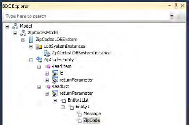
Next, the identifier for the Finder method return parameter is set for the entity. This is done by selecting the Identifier1 node under the Finder method return parameter for the ZipCodesEntity. Then, in the Properties window, change the Name property to ZipCode, as shown in Figure 13.
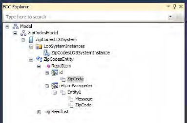
Next, set the identifier
for the specific Finder method return parameter and the input parameter
in the entity. To do so, first select the Identifier1 nodes under the specific Finder method return parameter for the ZipCodesEntity. Then, in the Properties window, change the Name property to ZipCode, as shown in Figure 14.
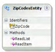
Right-click Identifier1, and select Rename in the BDC Designer (Figure 15). Change the identifier to ZipCode.
The message parameters are
not needed, so they should be removed. Right-click the message parameter
on the Finder method, and select Delete. This removes the Message node
from the BDC Explorer. Repeat this on the specific Finder method.
Alternatively delete the entity, and recreate a new "empty" entity.
6.3. Adding Parameters to Map the Data Source
Parameters must be added that
map to the data in the zipcodes text file data source. In this example,
the only parameter to map is the city name.
In the BDC Explorer, right-click Entity1 and select Add Type Descriptor. In the Properties window, change the Name property to City and the Type Name property to System.String, as shown in Figure 16. Repeat this for the Finder and the Specific Finder methods.
6.4. Configuring the Finder Method Instance
The method instance
properties are configured from the BDC Method Details window. This
window is also new in VS 2010. Selecting a method in the BDC Designer
will display the corresponding method instances in the BDC Method
Details window, as shown in Figure 17.
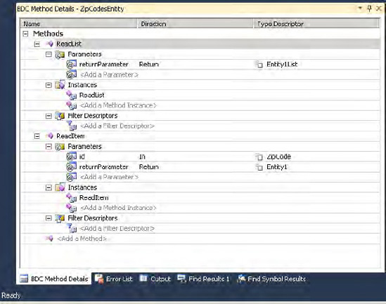
The Finder method is specified by setting the RootFinder
property on the Finder method instance. It specifies that this instance
is used to enumerate the items to crawl. If the Finder method instance
is not to be used for crawling, this property can be ignored and left
unset. Click the ReadList node in the BDC Method Details window. To set the RootFinder property on the Finder method instance, click the button in the Custom Properties row in the Properties window. Add the RootFinder property. Set the data type as System.String, and set the value to x, as shown in Figure 18.
If the data source contained data suitable for incremental crawls, the LastModifiedTimeStampField property on the Finder method instance could also be set. This is not feasible in this example.
7. Deployment
Deploying the .NET Assembly
Connector is made easy in Visual Studio 2010. Open the Build menu on the
top bar, and click Deploy Solution. Now VS 2010 begins to compile and
packages the .NET Assembly Connector code, BDC model, and the feature.
Finally it creates a WSP, which is the package type used for deploying
solutions to SharePoint.
The WSP package is then
deployed to the specified SharePoint site. The feature is activated,
which registers the external content type associated with this .NET
Assembly Connector.